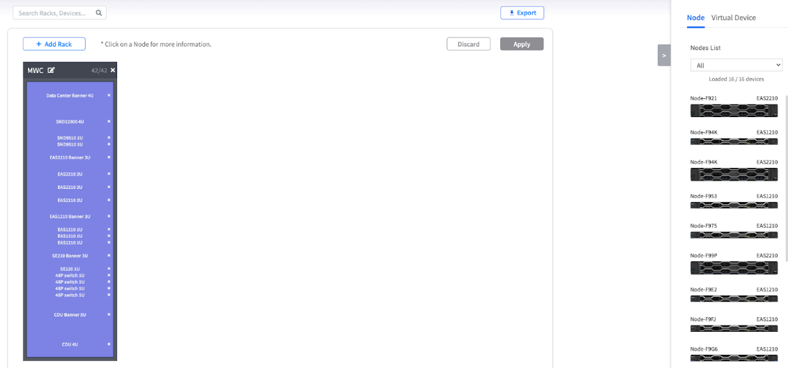
The main POD View interface, showing the rack canvas on the left and the device panel on the right.
| Use Case | Purpose | Benefits |
|---|---|---|
| Initial Data Center Design | Before any hardware is installed, use POD View and Virtual Devices to create a complete logical map of your planned environment | Plan layouts including servers, switches, and PDUs |
| Capacity Planning | As your infrastructure grows, use Virtual Devices to plan for future expansion and reserve rack space | Visualize future growth and space allocation |
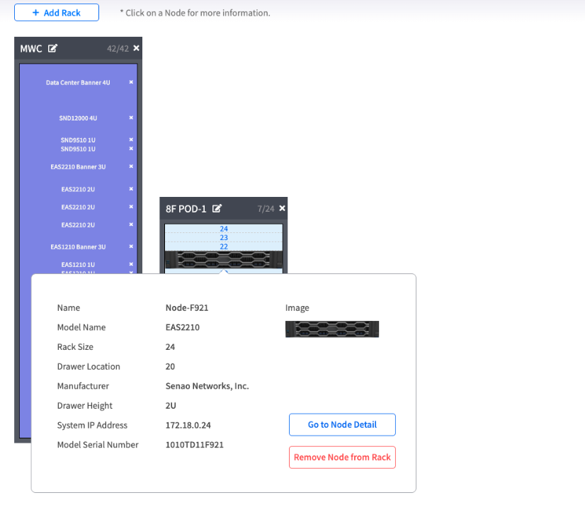
| Physical Maintenance & Identification | Help technicians quickly and accurately identify the logical location of a specific node within a rack | Reduce human error during physical work |
| Documentation and Reporting | Click the Export button to generate a PDF of your layout for official technical documentation | Create standardized rack documentation |
The main POD View interface, showing the rack canvas on the left and the device panel on the right.
| Tab | Content | Purpose |
|---|---|---|
| Node Tab | Lists all the real, managed EnGenius nodes in this POD | Place actual managed hardware |
| Virtual Device Tab | Contains non-real, placeholder devices you can create for planning | Plan for switches, firewalls, or future servers |
| Button | Function | Purpose |
|---|---|---|
| Add Rack | Opens the dialog to create new racks on your canvas | Create rack containers |
| Apply / Discard | Saves or cancels the changes you've made to your layout | Manage layout changes |
| Export | Allows you to export the current rack layout as a PDF document | Generate documentation |
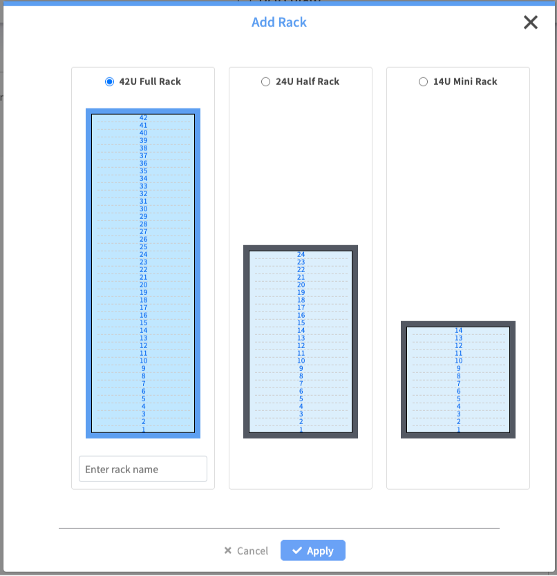
The "Add Rack" dialog showing the three rack type options.
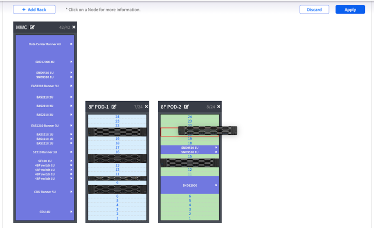
An animation or image showing a node being dragged from the Node List and dropped into a rack.
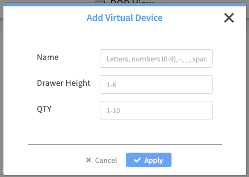
The "Add Virtual Device" dialog box.