Page cover
For the complete documentation index, see llms.txt. This page is also available as Markdown.

ECS8854F

Cloud Managed 48x SFP+ + 6x QSFP28 L3 Switch

Introduction

This Quick Start Guide is designed to guide you through the installation and initial configuration of the CloudSwitch Core 54, model ECS8854F.

CloudSwitch Core 54

Cloud Managed 48x SFP+ + 6x QSFP28 L3 Switch

Model: ECS8854F

  • 48 × 10G SFP+ ports

  • 6 × 100G QSFP28 uplink ports

  • EnGenius Cloud management support

  • Local Web GUI management support

  • Enterprise Layer 2 / Layer 3 networking capabilities

Package Contents

System Requirements

Web Browser

The following web browsers are recommended:

  • Google Chrome (57.0.2987.110 and later)

  • Microsoft Edge (80.0.361.103 and later)

  • Mozilla Firefox (52.0 and later)

Hardware Overview

Front Panel — Ports & Buttons

Rear Panel

LED Behavior Table

Hardware Installation

Before installation, make sure the installation site is clean, dry, well ventilated, and properly grounded.

Installation Environment

Install the switch in a clean, dry, and well-ventilated location. Make sure the operating environment meets the following requirements:

Item
Requirement

Operating Temperature

0°C to 50°C

Storage Temperature

-40°C to 70°C

Relative Humidity

5% to 95%, non-condensing

Power Input

AC 100–240V, 50/60Hz

To ensure reliable operation, keep the switch away from excessive dust, direct sunlight, heat sources, high humidity, and strong electromagnetic interference sources.

Installation Preparation

Before installing the switch, verify that the package contents are complete and prepare the required tools.

Recommended tools:

  • Phillips screwdriver

  • Flat-head screwdriver

  • ESD wrist strap

Use the mounting brackets and screws provided with the product. Standard network cables, fiber cables, and compatible transceivers should be used for installation.

Grounding the Switch

Before powering on the switch, connect the grounding point on the rear panel to a proper earth ground.

Proper grounding helps protect the device from electrical surges, electromagnetic interference, and potential safety risks.

Safety Information

  • Follow all safety instructions to prevent device damage or personal injury.

  • Do not block ventilation openings.

  • Keep the device away from excessive heat, moisture, conductive materials, and flammable materials.

  • Ensure proper grounding before operation.

  • Use properly grounded power outlets with overload protection.

  • Do not open the switch chassis.

  • Disconnect power before moving, servicing, or inspecting the device.

  • Do not look directly into optical transceiver ports or fiber connectors while the device is operating.

  • Use appropriate ESD protection when handling internal components.

  • Install the device in a clean and well-ventilated environment.

  • Inspect the installation environment periodically to ensure safe operation.

  • In an emergency, disconnect power immediately.

Rack Mount Installation

The ECS8854F is designed for installation in a standard 19-inch equipment rack.

  1. Attach the mounting brackets to both sides of the switch using the supplied bracket screws.

*The display model number may be varied according to different models.
  1. Place the switch into the rack and secure it using rack mounting screws.

  2. Ensure sufficient space around the switch for proper airflow and heat dissipation.

*The display model number may be varied according to different models.
The mounting brackets are designed to secure the switch to the rack and are not intended to support the full weight of the device. For additional stability, using a rack shelf or tray is recommended.

Power On Device

Before powering on the switch, make sure the power source is properly grounded and the input voltage is within the supported range.

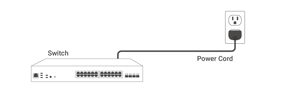
Connect the supplied power cord to the AC power socket on the rear panel of the switch, then plug the other end into a reliable AC power outlet.

The switch supports the following power input:

Item
Specification

Power Input

AC 100–240V, 50/60Hz

After power is applied, the switch performs a self-test and starts up automatically.

For more reliable operation, using an uninterruptible power supply (UPS) is recommended.

Improper grounding, unstable input voltage, or power surges may cause system errors or hardware damage.

Management Plane

EnGenius Cloud To-Go provides flexibility to manage your devices based on your network planning and deployment.

Option A: Cloud Management

Option B: Standalone Configuration

Cloud Management

Manage and monitor the switch through the EnGenius Cloud To-Go with a mobile app or through the web portal.

EnGenius Cloud To-Go (iOS/Android)

Standalone Configuration

You can connect a computer to the same network (subnet) as the switch and use a web browser to access the device's local web GUI for configuration whenever the device is in Standalone mode.

For CLI configuration in Standalone mode, please refer to CLI User Manual.

Option A: Configure with EnGenius Cloud

Step1: Register Device

You can register the device either by Cloud To-Go mobile app or the EnGenius Cloud platform.

Cloud To-Go Mobile App

You can register the switch with the Cloud To-Go app.

  1. Open and log in to the EnGenius Cloud To-Go mobile app.

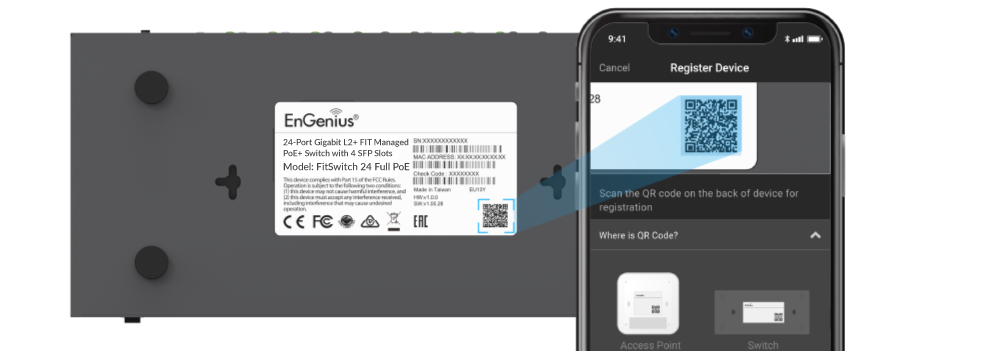
  2. Scan the QR code on the back of the device via the app.

3. If the camera successfully scans a QR code, the app will display the Device Information. You could tap "Register" to complete the Registration.

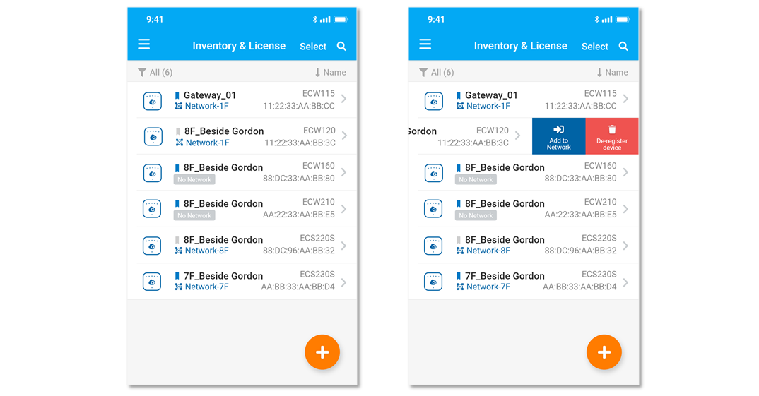
4. Registered devices will be shown on the Inventory&License page. Slide left the device and click "Add to Network" add the device to your personalized Network.

Network: Management domain shared same configurations within EnGenius Cloud.

EnGenius Cloud Platform

  1. Login into the EnGenius Cloud Platform: https://cloud.engenius.ai/

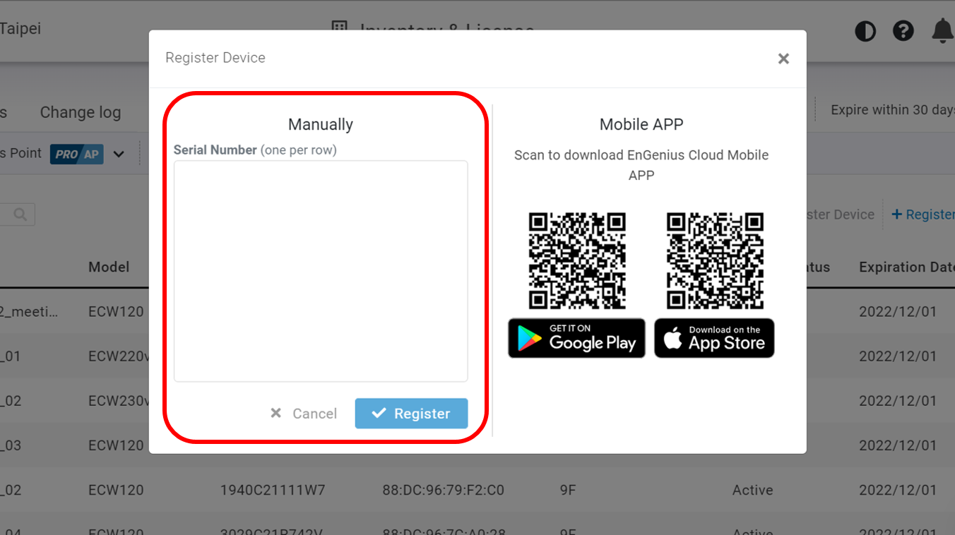
  2. Go to the home > Inventory page and click "Register Device".

  3. Enter the Serial Number of the device(s) for device registration. Please refer to "User Manual-Registering Devices to Organization".

4. Select the registered device and click "Assign to Network" to add the device to your personalized Network.

Network: Management domain shared same configurations within EnGenius Cloud.

Step 2: Connect to EnGenius Cloud

The switch supports management access through either the dedicated MGMT Port or the front-panel ports.

Interface
Default Setting

MGMT Port

IP Address: 192.168.100.1 / 255.255.255.255

Front-Panel Ports

All front-panel ports are members of VLAN 1 by default. The VLAN 1 interface operates as a DHCP client.

Note: The MGMT Port is a dedicated out-of-band management interface and operates independently from all front-panel VLAN interfaces. It does not participate in Layer 2 switching or Layer 3 routing, and traffic is not forwarded between the MGMT Port and any front-panel VLAN interface.

EnGenius Cloud Connected

Once the device is powered on and ready to connect to the Internet, It will automatically download the default configuration settings from EnGenius Cloud for automated provisioning.

When the Switch is connected to the EnGenius Cloud Platform for the first time, it will automatically check the latest available firmware. If the firmware upgrade is required, it might take 8~10 minutes to complete the process.

Step 3: Manage with the EnGenius Cloud

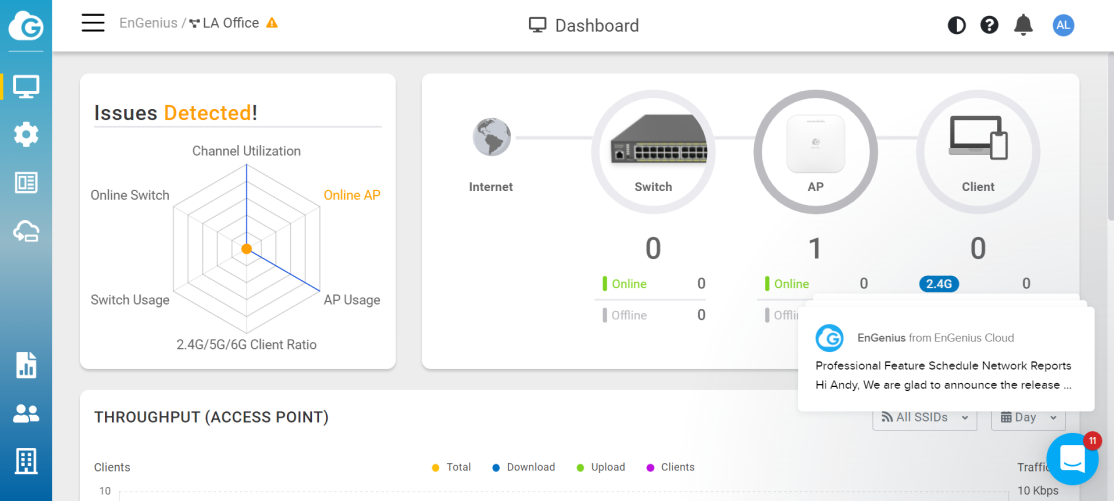
Log in to the EnGenius Cloud Platform to view the device in the Switch List. Currently, EnGenius Cloud only supports displaying the device in the Switch List and does not support direct configuration. To configure the switch, use the Local Web GUI or access the Remote CLI from the Switch List. For more information, please refer to User Manual.

Regulatory Statement

Last updated

Was this helpful?