> For the complete documentation index, see [llms.txt](https://doc.engenius.ai/llms.txt). Markdown versions of documentation pages are available by appending `.md` to page URLs; this page is available as [Markdown](https://doc.engenius.ai/s11-user-guide/reference/onboard-connectors-and-jumpers.md).
# Onboard Connectors & Jumpers
This chapter serves as a detailed hardware reference for the server's motherboard. Use these diagrams and tables to identify key internal connectors, headers, and jumpers for component installation, system configuration, and advanced troubleshooting.
## **Motherboard Layout Overview**
Before performing any procedures, please refer to the diagram below to understand the relative locations of key components. All detailed descriptions that follow are based on this layout.
## **Power Connectors**
* **24-pin ATX Power Connector (PWR1):** Supplies main system power.
* **8-pin CPU Power Connector (PWR2):** Supplies dedicated power to the processor(s).
* **Optional 4-pin or 8-pin AUX Connector (PWR\_AUX):** Provides auxiliary power for high-load GPUs or riser cards.
## **Fan Headers**
The motherboard provides dedicated 4-pin fan headers for the system cooling modules. Fan speed is monitored via the BMC and adjusted automatically or via user-defined profiles.
* **FAN1 – FANx:** System and CPU zone fan headers (PWM-controlled).
## **Front Panel Header**
This header connects the chassis control panel cables to the motherboard. The front panel header typically includes pins for:
* Power switch
* Reset switch
* HDD activity LED
* Power status LED
* NMI (if supported)
## **Storage Connectors**
These high-speed headers are used to connect the motherboard to the backplane for storage interfaces.
## **Peripheral & Security Headers**
* **USB 2.0 / 3.0 headers:** For internal USB connections (e.g., a bootable USB key).
* **TPM header (JTPM1):** For installing a Trusted Platform Module 2.0, typically a 14-1 pin header.
* **BMC Force Recovery / BIOS Recovery Jumpers:** Used for advanced firmware maintenance.
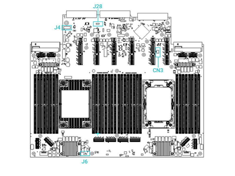
## **Jumper Settings**
This header shows where to find key jumper settings on the motherboard and what each one does. For accuracy, always check the system block diagram or silkscreen labels before making changes.
Jumper Name
Pins
Function
Default State
J4
3-pin
Clear BIOS password
Pins 1–2 shorted (Normal)
J6
3-pin
Clear CMOS
Pins 1–2 shorted
J28
3-pin
PM_BUS for debug
Open
CN3
4-pin
VROC hardware key
Open
{% hint style="info" %}
**Jumper Configuration Notes:**
* Use jumpers only when directed by support documentation.
* Always power off and disconnect the system before changing jumper settings.
* After using J4 (Password Clear) or J6 (Clear CMOS), return the jumper to its default position (Pins 1–2).
* CN3 is only used when enabling Intel VROC via hardware key.
{% endhint %}
Jumper Name
Pins
Function
J4
1–2
Normal operation (default)
J4
2–3
Clear BIOS password
Jumper Name
Pins
Function
J6
1-2
Normal operation (default)
J6
2-3
Clear BIOS password
Jumper Name
Pins
Function
J28
1
PMBUS SCL
J28
2
PMBUS SDA
J28
3
GND
Jumper Name
Pins
Function
CN3
1
GND
CN3
2
3.3V
CN3
3
GND
CN3
4
VROC_HW_KEY
## Detailed Interface Specifications
This section provides comprehensive technical details for the various onboard interfaces.
### **Header Summary**
|
Header Name (Silkscreen ID)
| **Location (General)** | **Function** | **Control Type / Interface** |
| ------------------------------------------------------- | ---------------------- | -------------------------------- | ---------------------------- |
| **JFP1** | Front panel corner | Power/reset buttons, LED control | BMC / GPIO |
| **FAN1–FAN6** | Near CPU zones & edge | 4-pin PWM system fan control | BMC via SMBus |
| **USB2\_HDR** | Near DIMM slot A1 | Internal USB 2.0 port | PCH / Southbridge |
| **TPM\_HDR** | Near PCH or DC-SCM | TPM 2.0 module interface | LPC interface |
| **CPU\_PWR1 / ATX\_PWR1** | Board edge (top right) | Main power and CPU voltage input | PSU direct |
| **BMC\_CON** | Near AST2600 | BMC debug/UART console | BMC UART1/2 |
| **MCIO\_1–MCIO\_8** | Near CPU + rear side | High-speed PCIe NVMe interface | CPU PCIe lanes |
### **Interface Capabilities**
| **Connector Type** | **Signal Type** | **Max Bandwidth** | **Usage** |
| -------------------------- | ------------------ | ----------------- | ---------------------------------------- |
| **MCIO x8** | PCIe Gen4 x4 or x8 | Up to 64 GT/s | NVMe SSDs (U.2/U.3) |
| **SFF-8639 (U.2)** | PCIe | PCIe Gen5 x4 | Front hot-swap drive bays |
| **PCIe x16 (gold-finger)** | PCIe Gen5 | Up to 128 GT/s | GPU, RAID, high-performance add-in cards |
| **OCP NIC 3.0 (Type 1A)** | PCIe Gen4 x8 | Up to 64 GT/s | Modular network interface |
| **RJ45 (BMC/IPMI)** | Ethernet 1GbE | 1 Gbps | Out-of-band management |
| **USB 3.2 Gen1 Type-A** | USB | 5 Gbps | External peripherals (keyboard, flash) |
| **Mini Display Port** | - | N/A | Local console display via BMC AST2600 |
| **USB 3.0 Type A** | - | - | - |
| **4-pin PWM Header** | PWM + TACH | N/A | System fan power and speed feedback |
| **LPC TPM Header** | LPC | N/A | Trusted Platform Module (TPM 2.0) |
## **Specialized Modules & Interfaces**
### **DC-SCM (Data Center Scalable Control Module)**
This server supports a modular DC-SCM, an OCP-standardized module for server management, security, and control functions. Its main components include:
* BMC (ASPEED AST2600)
* 8GB eMMC storage
* TPM (via LPC interface)
* UART, JTAG, and Reset interfaces
### **PIC\_PWR Connector (12V Output)**
The DC-SCM module includes a 2-pin power header, `PIC_PWR (J9)`, which can supply 12V DC to connected peripheral cards, such as an OCP NIC.
### **SMBus Interfaces to PCIe Riser Cards**
The system provides dual-channel SMBus connections to each PCIe riser card for FRU (Field Replaceable Unit) information, temperature monitoring, and hot-swap presence detection.
| Riser Slot | Channel A (SCL/SDA) | Channel B (SCL/SDA) |
| ----------- | ----------------------------- | ----------------------------- |
| **Riser 1** | SMB\_RISER1\_A\_LVC3\_SCL/SDA | SMB\_RISER1\_B\_LVC3\_SCL/SDA |
| **Riser 2** | SMB\_RISER2\_A\_LVC3\_SCL/SDA | SMB\_RISER2\_B\_LVC3\_SCL/SDA |
| **Riser 3** | SMB\_RISER3\_A\_LVC3\_SCL/SDA | SMB\_RISER3\_B\_LVC3\_SCL/SDA |
| **Riser 4** | SMB\_RISER4\_A\_LVC3\_SCL/SDA | SMB\_RISER4\_B\_LVC3\_SCL/SDA |
| **Riser 5** | SMB\_RISER5\_A\_LVC3\_SCL/SDA | SMB\_RISER5\_B\_LVC3\_SCL/SDA |
| **Riser 6** | SMB\_RISER6\_A\_LVC3\_SCL/SDA | SMB\_RISER6\_B\_LVC3\_SCL/SDA |
---
# Agent Instructions
This documentation is published with GitBook. GitBook is the documentation platform designed so that both humans and AI agents can read, navigate, and reason over technical content effectively. Learn more at gitbook.com.
## Querying This Documentation
If you need additional information that is not directly available in this page, you can query the documentation dynamically by asking a question.
Perform an HTTP GET request on the current page URL with the `ask` query parameter, and the optional `goal` query parameter:
```
GET https://doc.engenius.ai/s11-user-guide/reference/onboard-connectors-and-jumpers.md?ask=&goal=
```
`ask` is the immediate question: it should be specific, self-contained, and written in natural language.
`goal` is optional and describes the broader end goal you are ultimately trying to accomplish on behalf of the user. GitBook uses it to tailor the answer towards what is most useful for that goal.
The response will contain a direct answer to the question and relevant excerpts and sources from the documentation.
Use this mechanism when the answer is not explicitly present in the current page, you need clarification or additional context, or you want to retrieve related documentation sections.


.png)


